
Arduino - Step Motor + 74HC595 Pin Extender
SummaryIn this blog, I am going the test a Step Motor that rotates. I am also going to explore the pin extender chip, 74HC595. Then rewrite the clock sketch using 74HC595 chip to reduce the number of pins used.
Step Motor ExampleA step motor can precisely rotate the number of required steps (or angle). Using the Stepper.h library, it is very easy to control the motor. Below is a sample program to turn the motor half circle every 3s.
#include <Stepper.h>
#define MAX_MOTOR_STEPS 32
#define OUTPUT_STEPS_PER_REVOLUTION 2048

Stepper motor(MAX_MOTOR_STEPS, 8, 9, 10, 11);

void setup() {
  motor.setSpeed(600);  // Number of steps per minute
}

void loop() {
  motor.step(OUTPUT_STEPS_PER_REVOLUTION / 2);
  delay(3000);
}
MAX_MOTOR_STEPS - Is the motor's internal number of steps per revolution OUTPUT_STEPS_PER_REVOLUTION - Is the output number of steps per revolution
motor.setSpeed(600) - Sets speed in number of steps per minute
motor.step(num_of_steps) - Ask the motor to turn the number of steps. +turn clockwise, -ccw.
Material List and connection diagram
- 1x28BYJ-48 Step motor
- 1xULN2003APG motor controller chip

The problem is that line colorings can be different from different suppliers. For example, I got 2 examples of different coloring below

In general, follow the pin number as marked on the motor in the above picture to connect to the Adruino pins. If it does not work, try different combinations. If you get the incorrect connection, it will not damage the motor. So you can always try different combnations until it works.
74HC595 Pin Extender
The 74HC595 chip can be used to extend the number of (output) pins. For the MCU, it has max of about 20 pins. This is limited in many appications. The 74HC595 uses 3 pins of the MCU. It can turn that to 8 output pins. The best thing with this chip is that you can chain more chips to add more and more pins, while till using 3 pins from your MCU.
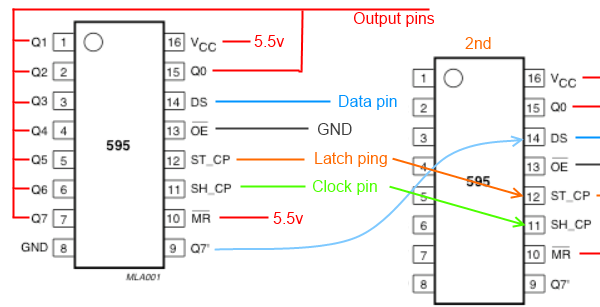
The following is the 74HC595 chip's pin arrangement:
- Vcc -- connects to 5.5v
- GND -- Connects to GND
- Q0-Q7 -- are the 8 output pins
- DS -- Is the so called input data pin. This pin accepts 1 byte of data (8bits) that determines the 8 output pin's status (1-HIGH, 0-LOW).
- ST_CP -- The so called latch pin. When the pin is set to LOW, the chip accepts data on the data pin. When set to HIGH, it flushes the data out to the 8 output pins.
- SH_CP -- The so called clock pin. I am not sure about its meaning. But its needed.
- Q7" -- Serial out pin. The pin, if used, cnnects to the DS pin of the next chip in the chain. Its function is to "shift" the data byte to the next chip. So the 74HC595 chip is also called "Shift Register" chip.
The normal code sequence to use the 74HC595 chip is shown in the following code fragment:
digitalWrite(latchPin, LOW);  // St to LOW to accept data
shiftOut(dataPin, clockPin, MSBFIRST, byte_1);  // Send data byte 1 to chip 1
shiftOut(dataPin, clockPin, MSBFIRST, byte_2);  // Shift data byte in chip 1 to chip 2,
                                                // then send data byte 2
// As many shiftOut() calls as there are number of chips in the chain.
digitalWrite(latchPin, HIGH); // Sets all output pins to HIGH or LOW according to the data bytes
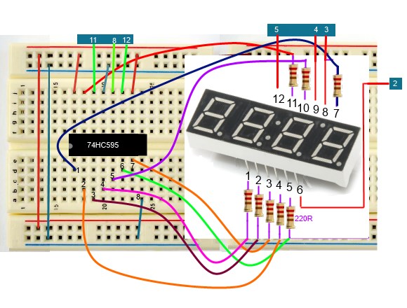
Rewiting the Clock Sketch with 74HC595 Chip
In the previous clock sketch, we used 12 pins to control the 4 digit display. By using a 74HC595 chip, the number of pins can be reduced to 7 : 4 block pins + 3 pins for the shift register chip. The connection diagram is shown below:
Source Code
byte pinBlocks[4] = {5, 4, 3, 2};
// Bits for displaying number 0~9
byte bits_onoff[10] = {63, 6, 91, 79, 102, 109, 125, 7, 127, 111};
int latchPin = 8;
int clockPin = 12;
int dataPin = 11;

byte dot_time = 0;  // <75 dot on, >=75 dot off
byte hhmm[4] = {1, 2, 0, 0};
byte num_switch_count=0;  // Number of continuous switch on

volatile short seconds_count = 0;

#define CPU_HZ 16000000
#define timer_hz 5
#define switchPin 0

void setup() {
  for(int i=0; i<4; i++){
    if(i<4) pinMode(pinBlocks[i], OUTPUT);
  }
  pinMode(latchPin, OUTPUT);
  pinMode(clockPin, OUTPUT);
  pinMode(dataPin, OUTPUT);
  setInterruptTimer();
//  Serial.begin(9600);
}

void loop() {
  for(int i=0; i<4; i++) {
    if( i==0 && hhmm[0] == 0) { delay(4); continue; }
    showNumber( hhmm[i], i==1 && dot_time < 40);
    blockOn(i);

    delay(4);
  }
  dot_time++;
  if( dot_time > 100) dot_time = 0;
}

// Clears a block by writing the given block pin LOW, others HIGH
void blockOn(int blkn){
  for(int i=0; i<4; i++) digitalWrite(pinBlocks[i], HIGH);
  digitalWrite(pinBlocks[blkn], LOW);
}

// Show a single number: 0~9
void showNumber(int num, bool show_dot){
  digitalWrite(latchPin, LOW);
  // shift out the bits:
  shiftOut(dataPin, clockPin, MSBFIRST, bits_onoff[num] + (show_dot ? 128:0));
  // take the latch pin high so the LEDs will light up:
  digitalWrite(latchPin, HIGH);
}

// Setup timer1 so that interrupts hz times per second
void setInterruptTimer(){
  noInterrupts();

  TCCR1A = 0;// set entire TCCR1A register to 0
  TCCR1B = 0;// same for TCCR1B
  TCNT1  = 0;//initialize counter value to 0
  // set compare match register for 1hz increments
  OCR1A = CPU_HZ / 1024 / timer_hz - 1; // must be <65536
  // turn on CTC mode
  TCCR1B |= (1 << WGM12);
  // Set CS12 and CS10 bits for 1024 prescaler
  TCCR1B |= (1 << CS12) | (1 << CS10);
  // enable timer compare interrupt
  TIMSK1 |= (1 << OCIE1A);
  interrupts();
}

// interrupt service routine called automatically every timer tick.
ISR(TIMER1_COMPA_vect){  //timer1 interrupt 1Hz
  seconds_count++;
  if(seconds_count == 60 * timer_hz) {
    seconds_count = 0;
    addMinute(1);
  }
}

void addMinute(int m) {
   hhmm[3] += m;
   if(hhmm[3] > 9) { // 10m
     hhmm[3] = 0;
     hhmm[2]++;
     if(hhmm[2] == 6) {
       hhmm[2] = 0;
       addHour();
     }
   }
}
void addHour(){
   hhmm[1]++;
   if(hhmm[1] > 9) { // 10h
      hhmm[1] = 0;
      hhmm[0]++;
   }
   else if(hhmm[1] == 4 && hhmm[0] == 2){  // 24h
      hhmm[0] = hhmm[1] = 0;
   }
}
| Prev |