
Arduino - Programming an MCU (Atmeg328p)
SummaryOnce we have developed and tested a project, we need to copy the code onto a new MCU to be used on a breadboard separate from the Arduino Board. This exercise describes one way of downloading the program onto a new MCU.
Material List- 1 x Unprogrammed Atmega 328P-PU. No bootloader is necessary.
- 1 x 10K resistor
- 1 x 16MHz occillator to be used as an external clock.
- 2 x 18~22 picofarad (ceramic) capacitors.
Setup Arduino Uno board as an ISP programmer
- In Arduino IDE, File -> Examples -> Arduino ISP
- Tools -> Board -> Arduino Uno
- Tools -> Programmer -> Arduino as ISP
- Note down serial port number (most likely COM3)
- Check settings as show in the screen shot below. Then click [Upload].

The Arduino is now loaded a program that can act as an ISP programmer.
Wiring the H/W components
I am using a smaller breadboard and try to setup a more permanent configuration so that I can reuse more conveniently in the future. The component layout is slightly different, but the connections are the same.

Compile Sketch and Locate hex File
The following sketch lets an LED attached to pin 12 blink.
int i;
int ledpin=12;

void setup() {
  pinMode(ledpin, OUTPUT);
}

void loop() {
    for(i=0; i<2; i++)
    {
      digitalWrite(ledpin,HIGH);
      delay(250);
      digitalWrite(ledpin,LOW);
      delay(250);
    }
    delay(2500);
}
The output of compiling a sketch is a HEX file. The hex file contains machine instructions. When uploaded to an MCU's flash memory, it will start executing when powered on.
To located the output file, you need to turn on
File -> Peference -> Settings -> Show verbose output during compilation.
The you can locate the hex output file, it is in my case :
C:\Users\AndrewQu\AppData\Local\Temp\build7b27b474b023374a5b7498d9f754d24c.tmp\blink.ino.hex
Copy the fle to c:\temp\blink.ino.hex
Using avrdude to Write the hex file to Atmeg328P-PUFirst install the latest WinAVR package. You can download from the internet. Once installed, open a command prompt and type avrdude. If the program is installed correctly, it should display some program help information.
Turn on the wired Arduino board. Leave the Arduino IDE on and check the port number. Assume it is COM3. Type the following command:
C:\>avrdude -P COM3 -b 19200 -c avrisp -p m328p -n
avrdude: AVR device initialized and ready to accept instructions
Reading | ################################################## | 100% 0.08s
avrdude: Device signature = 0x1e950f
avrdude: safemode: Fuses OK
avrdude done.  Thank you.
You are ready to proceed. Simply type the following command:
C:\>avrdude -P COM3 -b 19200 -c avrisp -p m328p -u -U flash:w:"c:\temp\blink.ino.hex":i
avrdude: verifying ...
avrdude: 1112 bytes of flash verified
avrdude done.  Thank you.
Now the Atmeg328 MCU is programmed with the led blink sketch.
Verifying the MCU has been programmed properblyWe'll verify that the above procedure worked and the programmed MCU can actually work. In a standalone project, we would required some sort of power supply. In this case, we'll simply use the Arduino's power supply.
Remove the programmed MCU and put onto a different bread board. Connect the crystal and capacitators as shown in Fig.1, except lines 10,11,12,13.
To connect the LED to the correct pin, we need the Arduino pin mapping as shown below:

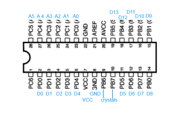
From that, we see that we need to connect the LED to pin 18 on the Atmega328 MCU. The final connection diagram will look like in the picture below.

If the LED blinks, then we have completed the MCU programming correctly.
| Prev | Next |