
Start Learning Arduino - More Experiments
SummaryMore Arduino exercises: Using a potentiometer to control the brightness of LED.
Using a Potentiometer to Control the brightness of LEDIn the past exercises, we either turn on the LED or turn it off using digitWrite(). Now we want to control the brightness of the LED. This can be achieved by using analogWrite(pin, val), where val is in the ranage of 0~255.
Further more, we want to use a potentiometer to manually control the brightness. A potentiometer can change the output voltage and send the value to an analog pin (in the range og 0~1024). When the knob is turned, voltage can change. We can read this value from the analog pin, then using this value, set the brightness of the LED light.
Wiring diagram
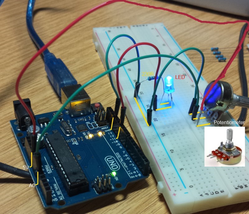 Fig. 1
The Normally, you would solder wires to the 3 legs of the potentiometer. I found that I can simply plug the legs into the holes of the bread board. One side leg of the potentiometer is connected to the 5V pin. The other side leg is grounded. The middle leg connects to pin A0 and output the changed voltage, depending on the knob position. LED connection is the same as before. Please also notice that the holes on the top and bottom 2 rows are connected internally.
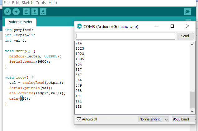
Skecth and OutputThe sketch for this exercise is shown below:
int potpin=0;
int ledpin=11;
int val=0;

void setup() {
  pinMode(ledpin, OUTPUT);
  Serial.begin(9600);
}

void loop() {
  val = analogRead(potpin);
  Serial.println(val);
  analogWrite(ledpin,val/4);
  delay(10);
}
As usual, compile and upload the sketch. Once program is running, turn the knob of the potentiometer to see the brightness of the LD changes. Now turn on the Serial Monitor, we can see the values read from the potentiometer, ranging from 0~1023.
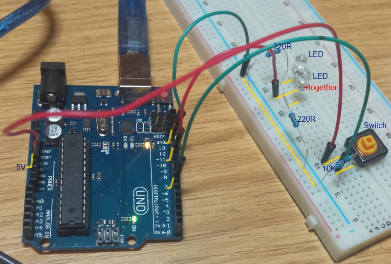
In this exercise, I am going to use a switch to turn on/off the 2 LEDs. A switch has 2 pairs of legs. The leges are marked 1 to 4. 1-2 are internally connected. 3-4 are alson internally connected. When the buton is not pressed, 1-3, 2-4 are not connected. When pressed, all 4 leges become connected. I will use this as toggle switch. That is, the LEDs are initially turned off. Press the switch once, the LEDs turned on. Press again, turned off, and so on.
The wiring diagram is as follows. Please note, I am using 2 LEDs whose + legs are connected to pin 11 and - legs are connected to a 220R and then grounded.
The Code
int ledpin=11;
int val=0;
int switchpin=7;
int led_on=0;

void setup() {
  pinMode(ledpin, OUTPUT);
  pinMode(switchpin, INPUT);
}

void loop() {
  val = digitalRead(switchpin);
  if(val==HIGH) {
    digitalWrite(ledpin, led_on==0 ? HIGH : LOW);
    led_on = 1-led_on;
    delay(1000);
  }
  delay(5);
}
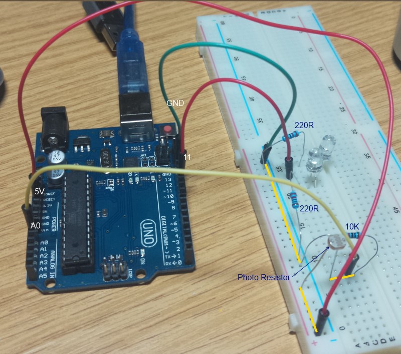
Photo Resistor
A photo resistor changes its resistance value as ambient brightness changes. We can read its value from an analog pin. According to the value, we set the LED brightness.
Wiring Diagram
The Code
int lightPin = 0;  //define a pin for Photo resistor
int ledPin=11;     //define a pin for LED

void setup()
{
    Serial.begin(9600);  //Begin serial communcation
    pinMode( ledPin, OUTPUT );
}

void loop()
{
    int val=analogRead(lightPin);
    Serial.println(val);
    analogWrite(ledPin, val/4);
    delay(10);
}
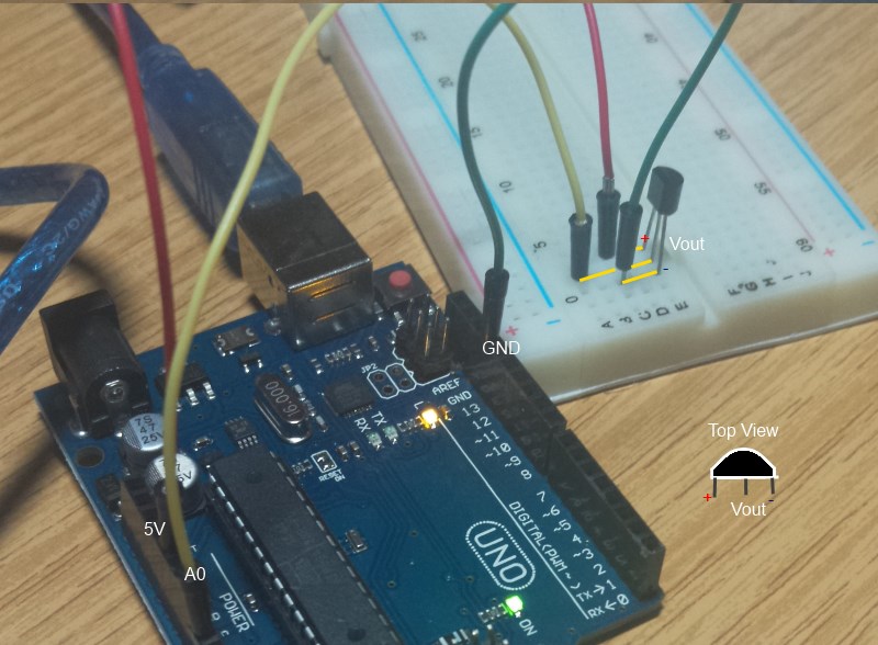
LM35 Temperature Sensor
This sensor takes the room temperature and converts the temperature to voltage. When viewed towards the flat face of the semi-cylinder, left legs is +, right leg is negative and th middle leg is Vout (range 0-1023). When the value is 1023, the voltage is 5V. Therefore,
mV = 5 * (val / 1024) * 1000
100mV = 1 °C
Therefore,
C = mV / 100;
Wiring Diagram
Code
void setup() {
  // put your setup code here, to run once:
   Serial.begin(9600);
}

void loop() {
  // put your main code here, to run repeatedly:
  int val = analogRead(0);
  float mv = 5000.0 * val / 1024.0;
  float centigrade = ((int)mv) / 100.0;
  Serial.println(centigrade);
  delay(2000);
}
Open the serial monitor, you should see the temperature readings.
END| Prev | Next |